Pool Controller
Archive repost from my old blog (2020). Original snapshot on the Wayback Machine.
At my parents’ house there’s a pool in the garden with an older controller for the filter pump and solar heating. Underground pipes pump the water from the skimmer and floor drain into the house, push it through the sand filter, heat it if needed - depending on how much solar heat is available - and return it to the pool through a few meters of pipe and the inlet nozzles.
The old controller is dead simple: a mechanical timer, an input for a temperature sensor, an output for the circulation pump of the heat exchanger, and a contactor-switched output for the filter pump. Most of the time, though, the pump gets switched on by hand - which means a walk down into the basement.
The concept
I wanted the new controller to be WiFi-capable and still cover everything the old one did. I started with a rough concept, then turned it into circuit schematics and designed boards for them.
There are actually two schematics and two boards: a base module built around a Wemos D1 mini, and a small DC-DC converter board (6-35V to 5V) that solders onto it.
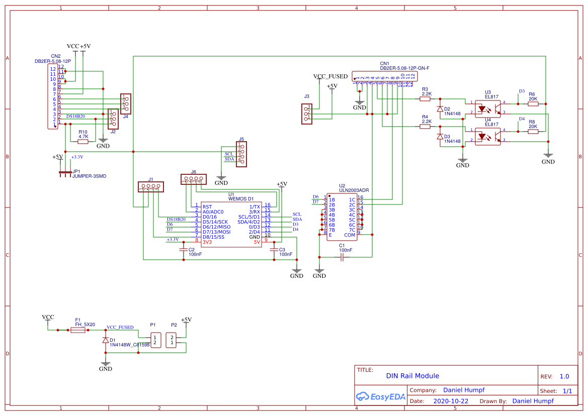 The base module schematic - Wemos D1 mini, optocoupler inputs, a ULN2003 driving the outputs
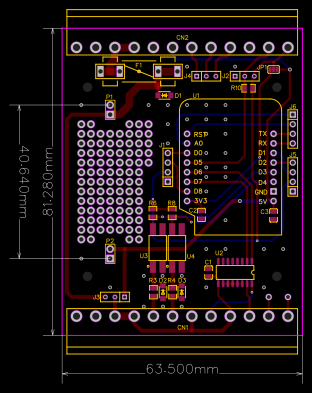 The base module board layout
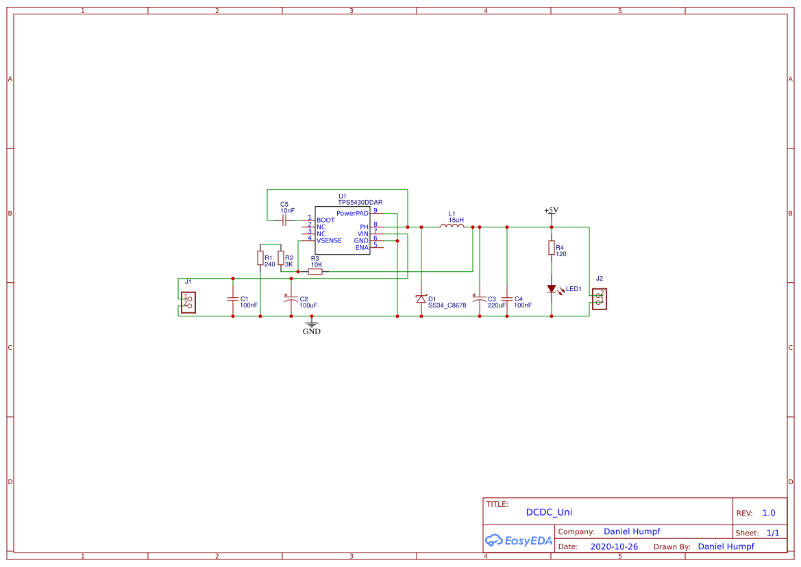 The DC-DC converter schematic, built around a TPS5430
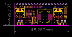 The DC-DC converter board layout
The build
I had the boards manufactured at JLCPCB. The DC-DC converters came back already assembled; the base modules I populated myself.
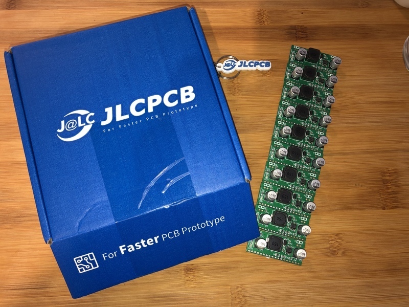 A panel of DC-DC converter boards, assembled at the fab
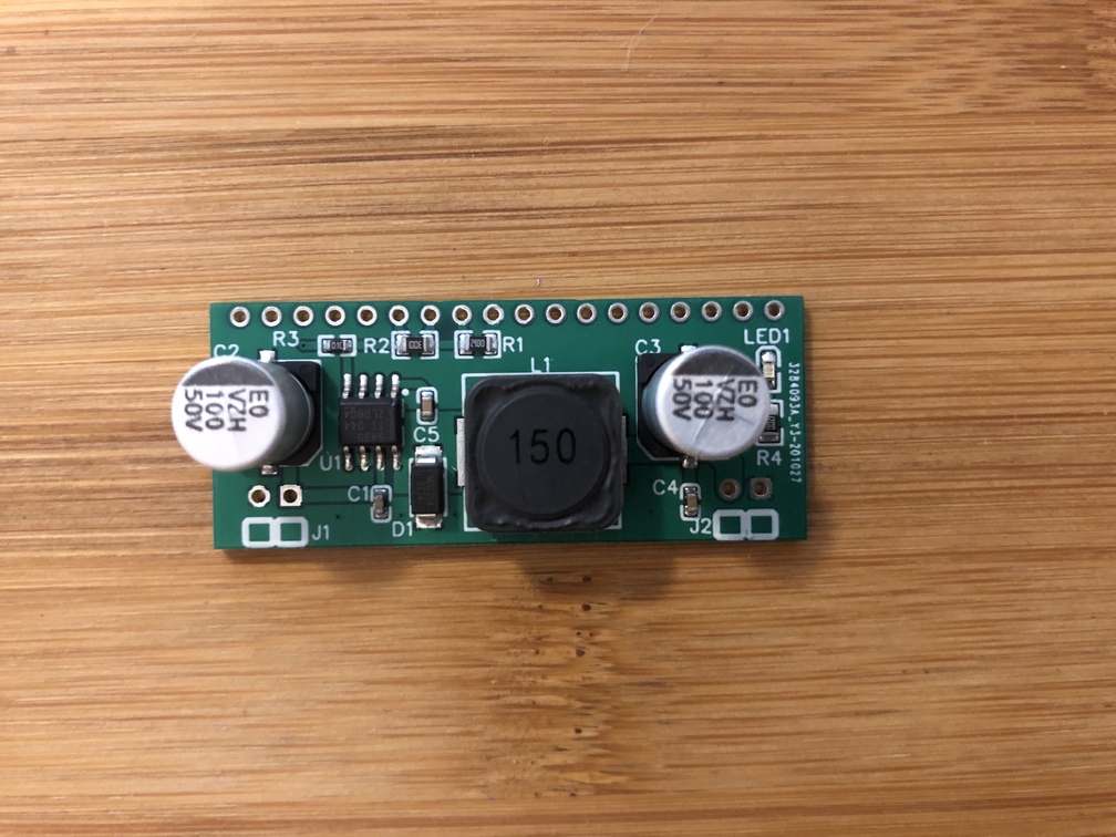 One DC-DC converter board - 6-35V in, a clean 5V out
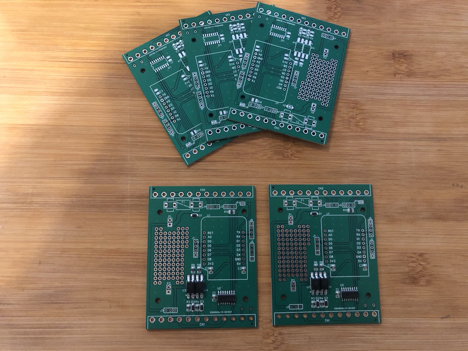 The bare base-module boards, back from the fab and ready to populate
Of course I made a mistake in the first revision - already fixed in the schematics above: the two optocoupler-isolated inputs were wired wrong on the Wemos board, so it reset itself continuously (D3/D4 pulled to ground through the pulldowns). I patched it with a bit of enameled wire near the two optocouplers.
Once a board was populated, I flashed the Wemos with a Tasmota build.
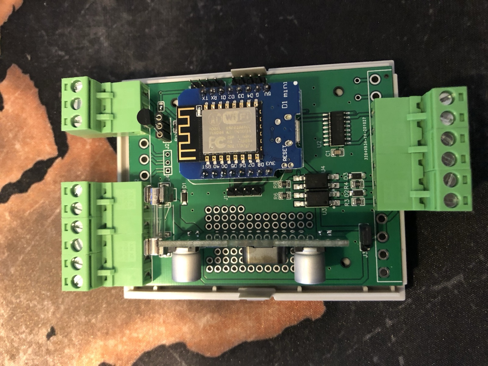 The assembled module with the Wemos D1 mini plugged in, sitting in its DIN-rail case
From there it went into a small distribution box, along with two auxiliary relays, a contactor, and a 24V power supply. The display, a button to switch the display on and off, and a potentiometer for setting the target temperature went into drilled and cut-out sections of the housing. The display flickers at a high frequency, so there’s always one black line in photos - the eye doesn’t notice it. A button for manually switching the filter pump on and off went into one of the cable entries on the box.
The result
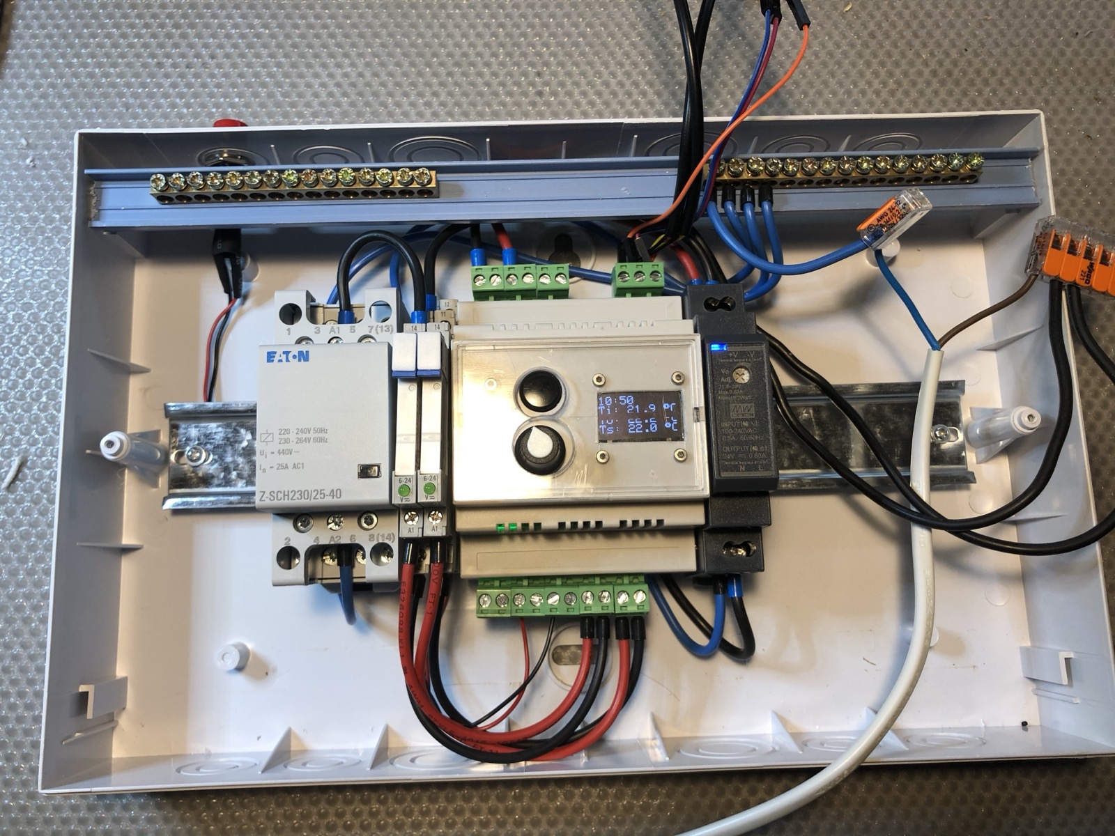 The finished controller - Eaton contactor, two auxiliary relays, a 24V supply, and the display showing live temperatures
The filter pump can now be switched three ways: by push button, through the web interface, and on a schedule with Tasmota. Depending on the water temperature and whether the solar system has excess heat to give, the circulation pump of the heat exchanger switches on as well.